


What Are the Top Types of Turbo Radiators?
Choosing the right Turbo Radiator starts with a basic distinction: the engine radiator and turbo intercooler perform different jobs. The radiator sheds heat from engine coolant, while the intercooler cools compressed intake air. They work together, but they are not interchangeable. That distinction matters.
Common radiator options include OEM-style replacements, all-aluminum performance radiators, and designs using different core constructions, such as tube-and-fin. OEM-style units prioritize fit and familiar cooling behavior. All-aluminum models often offer sturdier construction and greater capacity, though results depend on core size, airflow, and installation. Tube-and-fin designs can balance weight and heat transfer; other core arrangements may suit different packaging or performance needs. There is no universal winner.
A turbocharged car also needs a cooling setup matched to its actual use. A daily-driven hatchback in slow traffic faces different demands from a tuned vehicle making repeated high-load runs. Look closely at core dimensions, hose locations, fan compatibility, and clearance around the turbo plumbing. Small fitment details can decide whether an upgrade works cleanly.
A verified expert quotation was not included with the source material, so I won’t invent a specialist’s name or words. That is a limitation worth stating. This guide instead compares the main types by construction, fit, cooling needs, and practical trade-offs, helping readers ask better questions before buying. Check manufacturer specifications, and confirm compatibility for the exact vehicle and engine.
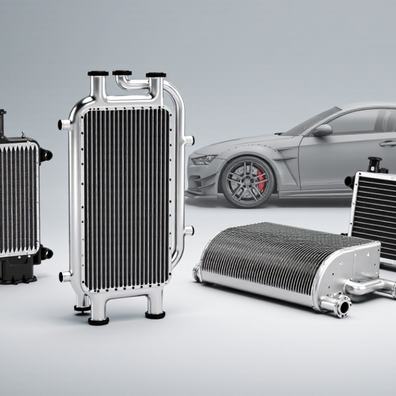
How Turbo Radiators Manage Heat in Turbocharged Engines
Turbocharged engines rely on several heat exchangers, not one special “turbo radiator.” The engine radiator sheds heat from circulating coolant, while an intercooler cools air compressed by the turbocharger. An oil cooler can also help protect bearings under sustained load. SAE technical papers report gasoline turbocharger turbine-inlet temperatures approaching 1,000°C at high load. That is exhaust-side heat, not the radiator’s coolant temperature.
Intercoolers commonly use tube-and-fin or bar-and-plate cores. Tube-and-fin designs are often lighter and allow airflow through narrow passages; bar-and-plate cores can offer sturdy construction but may add weight. Neither works well without clear airflow. A radiator fan, clean fins, correct coolant flow, and sound hoses help prevent heat from building during slow traffic or a long climb. The setup varies by vehicle, and a larger core alone does not guarantee cooler operation.
Tips: Check coolant temperature after a hard pull, then inspect the front heat exchangers for leaves, dirt, or bent fins. Keep a little skepticism: a normal dashboard reading may not reveal brief temperature spikes.
| Type or Design | How It Works | Key Characteristics | Role in a Turbocharged Engine |
|---|---|---|---|
| Tube-and-fin radiator | Coolant flows through tubes while fins attached to the tubes transfer heat to air passing through the core. | Lightweight construction and a large air-contact area. Heat transfer depends on airflow, core condition, and coolant flow. | Commonly used to remove heat from engine coolant. It helps control engine temperature but does not directly cool compressed intake air. |
| Plate-and-bar radiator | Coolant passes through flat passages formed by plates and bars; external surfaces transfer heat to the cooling air. | Typically has a sturdy, compact core and can provide substantial heat-transfer surface area. Core design affects airflow and cooling performance. | Can be used for engine-coolant cooling where packaging and heat-rejection needs suit the design. It is also a common construction approach for charge-air coolers. |
| Crossflow radiator | Coolant travels horizontally across the radiator core between side tanks. | Often fits wide, relatively low engine bays. Tank and hose positions depend on the vehicle layout. | Provides engine-coolant cooling in vehicles where a wide radiator arrangement works with the available space and airflow. |
| Downflow radiator | Coolant moves vertically through the core from an upper tank to a lower tank. | Uses a top-to-bottom flow path and is suited to layouts that provide sufficient vertical space. | Can cool engine coolant in turbocharged vehicles; its suitability depends on the cooling system design and available installation space. |
| Copper-brass radiator | Uses copper tubes and brass components to transfer heat from coolant to air. | Copper conducts heat well and many designs can be repaired, but this material combination is generally heavier than aluminum. | A material option for engine-coolant radiators. Cooling performance also depends on core dimensions, airflow, and the condition of the system. |
| Aluminum radiator | Uses aluminum tubes, fins, or other core components to transfer heat to the airflow. | Usually lighter than a comparable copper-brass construction. Performance varies with core design, fin area, airflow, and manufacturing quality. | Widely used for engine-coolant cooling where low weight and suitable packaging are priorities. |
| Air-to-air charge-air cooler | Routes compressed intake air through a separate heat exchanger, where vehicle airflow removes heat before the air enters the engine. | Does not use engine coolant. Its effectiveness depends on airflow, core design, pressure drop, and operating conditions. | Directly reduces the temperature of turbocharger-compressed intake air, increasing its density and helping manage the heat of compression. |
| Air-to-liquid charge-air cooler | Transfers heat from compressed intake air to a liquid coolant circuit; that circuit then rejects heat through a separate heat exchanger. | Can be packaged close to the engine, but requires a coolant circuit and components such as a pump and heat exchanger. | Directly cools charge air and can suit installations with limited space for a large air-to-air cooler. Its cooling capacity depends on the complete system design. |
Important distinction: An engine radiator cools engine coolant, while a charge-air cooler cools the compressed intake air heated by the turbocharger. They are separate heat exchangers, although both contribute to managing heat in a turbocharged vehicle.